On the 12th, I was witness to assembly of the insert for the second Keck receiver: K1. This numbering was the source of much consternation and bikeshedding at the daily breakfast meetings (especially because the first receiver was K3…or the zeroth receiver, depending who you ask…and maybe on the time of day too).
Anyway, unlike the operations I aimlessly photographed on my first day, I vaguely knew what was happening this time. Thanks to everyone that humoured my silly questions and put up with my constant photographing.
Also, since this post is the first to borrow a picture from Don, I’ll give a shout out to Don’s site.
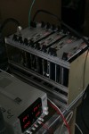
- Progress since the previous day: lights are now fullblinken
- MAPO is an old building, full of old and often questionably useful things. This is one of the more useful bookshelves I observed
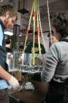
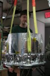
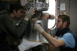
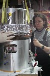
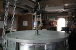
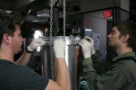
- The focal plane is lifted by the insert assembly team: Jamie, Sarah, Grant, Colin, and noisy hand-operated crane
- More lifting (and Colin). This is to emphasize the slowness of the crane. I can do nothing to convey the noisiness
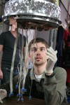
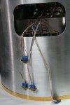
- Grant inspects the dangly cables
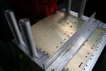
- The focal plane is set down on top of the fridge, etc
- This goes very slow to make sure that everything is aligned and nothing is pinched
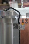
- Cables protrude out the side-hole until they’re connected
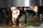
- With the outer shell lifted, I can see more cables and inline electronics modules
- Brief interlude of my work. This is jig for mounting the BLASTbus crate in the telescope mount. Darren and I were switching the (formerly deployed) test crate and (recently finished) deployment crate
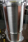
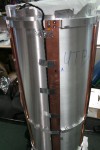
- Telescope tube, with copper heat straps along the side
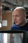
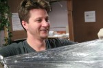
- Clem had showed up. I catch him behind the tube
- Chin-Lin inspects the tube before it is attached
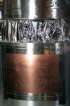
- The fridge area at the bottom is closed up with copper plates holding charcoal getter (getter sucks up helium to maintain vacuum)
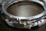
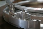
- Rotation mechanism for the half-wave plate. Spider will have similar ones, and this is the first I’ve seen in person
- Stepper motor drive mechanism for the rotator
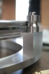
- One of three bearings that support the rotator itself
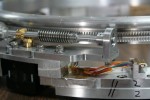
- Another of the bearings is spring-mounted, for a snug fit
- Lifting plate. For lifting
- The rotator is put in place so that the cables can be fit properly
- The now-fit cable, ready for the rotator to be remounted
- The cable runs up the side of the insert in the gap inside the vacuum vessel. Affixed with aluminum tape, this group’s tape of choice to use all over the place
- Jamie insulating with superinsulation (layers of aluminized mylar)
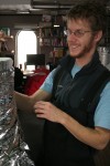
- Zak is the insulation master
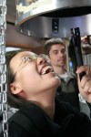
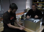
- In between picture taking, I find time to get some work done, with Darren (photo courtesy Don)


Leave a Reply